Improving tray efficiency by reducing weeping
Published by Callum O'Reilly,
Senior Editor
Hydrocarbon Engineering,
Distillation is the most widely used method for separating liquid mixtures into their individual components or fractions. As most distillation columns operating worldwide use trays to reduce their carbon footprint, it is imperative to maximise tray efficiency. One method is to reduce weeping thereby considerably reducing operating costs.
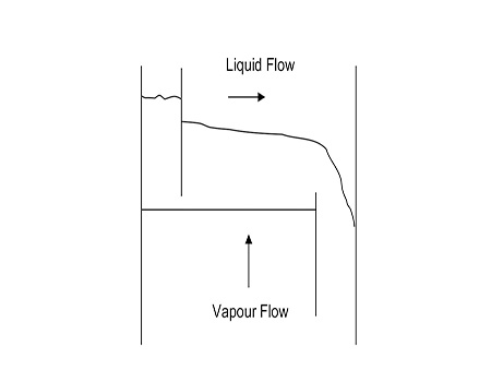
Figure 1. Schematics of a 1-Pass cross-flow tray.
Figure 1 shows a schematic representation of a 1-Pass cross-flow tray with liquid flowing from the inlet area to the downcomer (left to right). As the vapour passes through the active device and subsequent element of froth on the tray, mass transfer is effected, where light components (more volatile) are preferentially stripped out of the liquid phase whilst the heavy components (least volatile) are condensed out of the vapour phase.
With a trayed column there are three efficiencies of interest, the inter-relationship between which is given by the Lewis equations from 1936:1
- EOG Point Efficiency
- EMV Murphree Tray Efficiency
- EOC Overall Column (Section) Tray Efficiency
To maximise these efficiencies, complete contact is desired between the vapour and the cross-flowing liquid since any by-pass between the two will be detrimental. Under normal operation, all the liquid flows across the tray to the downcomer. To achieve this, a certain amount of vapour flow (dry pressure drop (ΔPdry)) is required. If the ΔPdry is too low, some liquid will weep through the active devices on the tray deck. At a very low vapour rate, the Dumping Point will be reached, particularly for sieve trays, where the ΔPdry may not be enough to keep any liquid on the tray deck and none flows over the weir into the downcomer.
Extent of weeping
To determine the effect of weeping on tray efficiency, initially a method of predicting the extent of weeping is required. Most correlations for predicting weeping do not quantify the amount but give a qualitative assessment whether a tray is weeping or not.
A rule of thumb the author has used in the design of trays in hundreds of columns is to limit the dry pressure drop to a minimum of 0.5 in. Liq. Although there may be some weeping at this operating point, the tray efficiency will be satisfactory.
Weeping from sieve trays

Figure 2. Schematic diagram showing pressure drop vs gas velocity for a cross-flow sieve tray – Prince, 1960.
Figure 2 from Prince, 1960, shows schematically the pressure drop characteristics of a cross-flow sieve tray.2 At very low rates all the liquid fed to a tray will fall through the holes. As the vapour rate is increased, the liquid encountering more resistance will eventually build-up a layer through which the vapour flows – Point A in Figure 2 is defined as the Seal Point. Further increases in the vapour rate will progressively reduce the amount of liquid weeping until the liquid height just reaches the exit weir height – Point B on Figure 2. Upon a further increase of the vapour rate, some liquid will flow into the downcomer until at Point C the Weep Point is reached when all the liquid flows into the downcomer. The pressure drop between Points B and C (the weeping range) will be more or less constant. From tests using five systems, in a 6 in. dia. glass column with 0.91 mm thick trays with three different sieve hole diameters – 0.063 in. (1.588 mm), 0.125 in. (3.175 mm) and 0.1875 in. (4.763 mm) – Prince determined Point C graphically from a plot of the total pressure drop. To prevent weeping, a recommendation was given to use a minimum F-factor through the hole (FH) of 8.2 ft/s (lb/ft3)0.5. For a standard sieve tray design (2 mm thick, 0.5 in. Ø holes, 10% open area) this is equivalent to a ΔPdry of 0.4 in. WG assuming an air-water system. This is an optimistic design limit as there will be significant weeping at this point. Branan, 1978, recommends a minimum FH factor of 12 which is equivalent to a ΔPdry of 0.9 in. WG for the same standard sieve tray design.3 This is a conservative design limit.
The criteria above, based solely on the reduced vapour hole velocity, ignore the liquid rate. However, ultimately the weeping rate is a balance between the force driving the liquid downwards through the holes (clear liquid head) and the forces opposing that (dry pressure drop plus surface tension force).....
Written by Aadam F. Aryan, Distillation Equipment Company Ltd.
This article was originally published in the March 2025 issue of Hydrocarbon Engineering magazine. To read the full article, click here.
For a full list of references, please click here.
Read the article online at: https://www.hydrocarbonengineering.com/special-reports/15122025/improving-tray-efficiency-by-reducing-weeping/
You might also like
The Hydrocarbon Engineering Podcast
p>A podcast series for professionals in the downstream industry featuring short, insightful interviews. Subscribe on your favourite podcast app to start listening today.
![]()
![]()
![]()
