Reciprocating compressors play a very important role in daily life, even if it is not always obvious. Only these types of machines can be used across several different refinery processes, such as for hydrotreating, hydrocracking, isomerisation, and catalytic reforming, much of which is intended for producing cleaner fuels. It is also the machine of choice for the green hydrogen energy market to reduce carbon emissions in the future.
The reason reciprocating compressors can uniquely serve these applications, among others, is due to their ability to deliver high pressure ratios and flexible capacity control, regardless of gas density. The complex rotating and reciprocating motion of the running gear components results in potential failure modes not seen in other machines, such as centrifugal compressors. Operators can use a variety of monitoring techniques to detect and diagnose specific faults, such as pressure and process parameters, but vibration monitoring remains the cornerstone of assessing the overall health of these compressors.

Figure 1. Crosshead vibration time waveform vs crank angle signal (blue). Here, the vibration signal is shown in plot form overlaying the rod load plot and head end (HE) and crank end (CE) pressure vs crank angle plots. The important crank angle impact events for the crosshead occur at the rod reversal points (shown as brown squares).
What to look out for
A reciprocating compressor vibration signature is very different from that of rotating turbomachinery, but it is just as important for effective monitoring. The impact forces generated by running gear clearance and looseness cause vibration peaks that operators can detect with an accelerometer. These impacts often excite high-frequency resonances, resulting in a ‘ringing’ effect with multiple peaks that gradually fade (see Figures 1, 2, and 3).
.jpg)
Figure 2. Vibration segment alarming. The segments can be set up with individual alarming limits to monitor specific impact events, in addition to the number of segments that are simultaneously in alarm, alongside the number of revolutions the segments remain in alarm.
Unlike rotating machinery signatures, the short-duration, high-acceleration impact peaks from reciprocating compressors are not so evident. The vibration amplitude of the narrow impact peaks contribute very little to the overall vibration signal response, therefore making it difficult to detect using standard overall vibration monitoring methods.
Monitoring vibration impacts allow operators to detect various failure modes much earlier (Table 1), but also present challenges. False machine trips can occur due to spurious peaks that are not related to an impending failure. While these peaks may still be valuable for condition monitoring, they must be filtered out for protective purposes.
.jpg)
Figure 3. Vibration segment function. For crosshead and cylinder acceleration, there are typically a total of 36 vibration segments to identify impacts. In this example, the time waveform signal is from the cylinder acceleration signal, where three segments are used to monitor the valve opening and closing events for both ends of the cylinder compression (HE = head end, CE = crank end).
Forces and potential component failure modes
Vibration impacts in reciprocating compressors are the result of forces acting on the running gear and cylinder, as shown in Figure 4. Distance piece looseness, component impacts (including liquid ingestion), gas pressure pulsations, and rotational forces can also affect these components. Monitoring these forces and their resulting symptomatic impacts is essential to prevent potential failure modes.
Potential failure modes
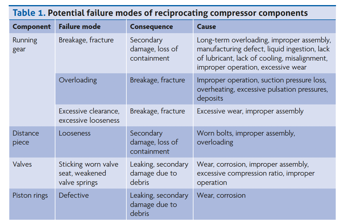
By only using accelerometers, there are several failure modes that operators can monitor in the crosshead, cylinder, and distance piece, as outlined in Table 1 and shown in Figure 5.
It is important to note that the potential failure modes for condition monitoring differ from those for protection. Some potential failure modes (such as misaligned cylinder liner, tilted crosshead) are only tracked for condition monitoring. While other modes – like seized pistons, liquid ingestion, or broken piston rods – are only monitored for protection. Defective compressor valves and loose running gear are monitored for both condition and protection.
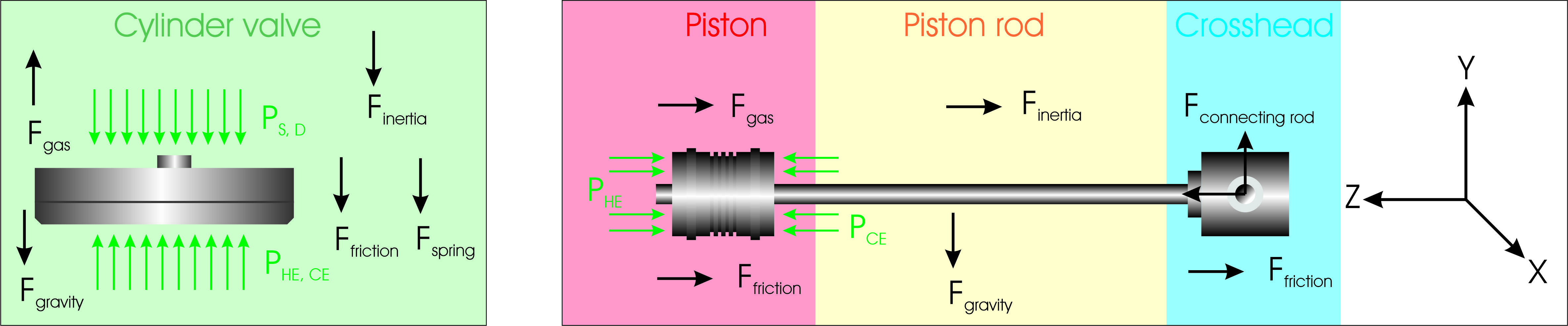
Figure 4. Forces acting on the valves (left) and the running gear (piston, piston rod, crosshead, right).
Condition monitoring techniques
Operators can monitor the crosshead, cylinder, and distance piece with one or two accelerometers and a tachometer for crank angle reference and triggering (Figure 5).
The raw signal, processed descriptors, and plots from these sensors include the following:
- Time waveform signals:
- Synchronised acceleration time waveform vs crank angle.
- Descriptors (in addition to standard descriptors such as overall vibration):
- Vibration segments.
- Impact count.
- Plots:
- Synchronised acceleration time waveform vs crank angle plot.
- Vibration segment vs crank angle plot.
- Trend plot.
The descriptors and plots, derived from the time waveform signal, detect the failure modes shown in Table 1.
Time waveform signals
The raw vibration signal from the crosshead and cylinder accelerometers is converted into a synchronised acceleration time waveform signal vs crank angle. This signal can be filtered and post-processed for further analysis and averaged according to the application needs. Filtering can also isolate non-synchronous vibration components. The synchronised one revolution vibration signal, itself synchronised to a phase trigger, is not monitored to limits.
Descriptors
There are several types of descriptors extracted from the accelerometer raw time waveform signals, but this article will focus only on vibration segments and impact count. The same descriptors are used for both condition monitoring and protection, but the signal filtering requirements are different for these two applications. To improve the reliability of the descriptors for condition monitoring, operators should process an average of the time waveform signal after a given number of revolutions.
Vibration segments
A synchronised complete crank revolution time waveform acceleration signal is calculated for each segment. Each segment can also be configured with its own alarm limits to individually monitor numerous crank angle events, as shown in Figures 2, 3, and 6. Vibration segments are ideal for monitoring specific crank angle events, such as valve opening/closing, rod reversals, top dead centre (TDC) and bottom dead centre (BDC) of piston, equalised pressure between cylinder pressure chambers, and rod load.
Impact count
As an alternative to the vibration segments, a non-synchronised signal can be used for automatic alarming based on vibration impact counting. If the vibration signal is properly filtered, this technique is well-suited for protection since spurious peaks are eliminated.
- The impact counting algorithm considers:
- Threshold: all peaks must be above a specified amplitude.
- Impact count: there must be more than one peak (typically eight) within the specified time period (window).
- Window: this is typically set to a time that corresponds to a part or several rotations of the crank.
It is difficult to generalise the impact of count configuration for all applications, so this is based on user experience.
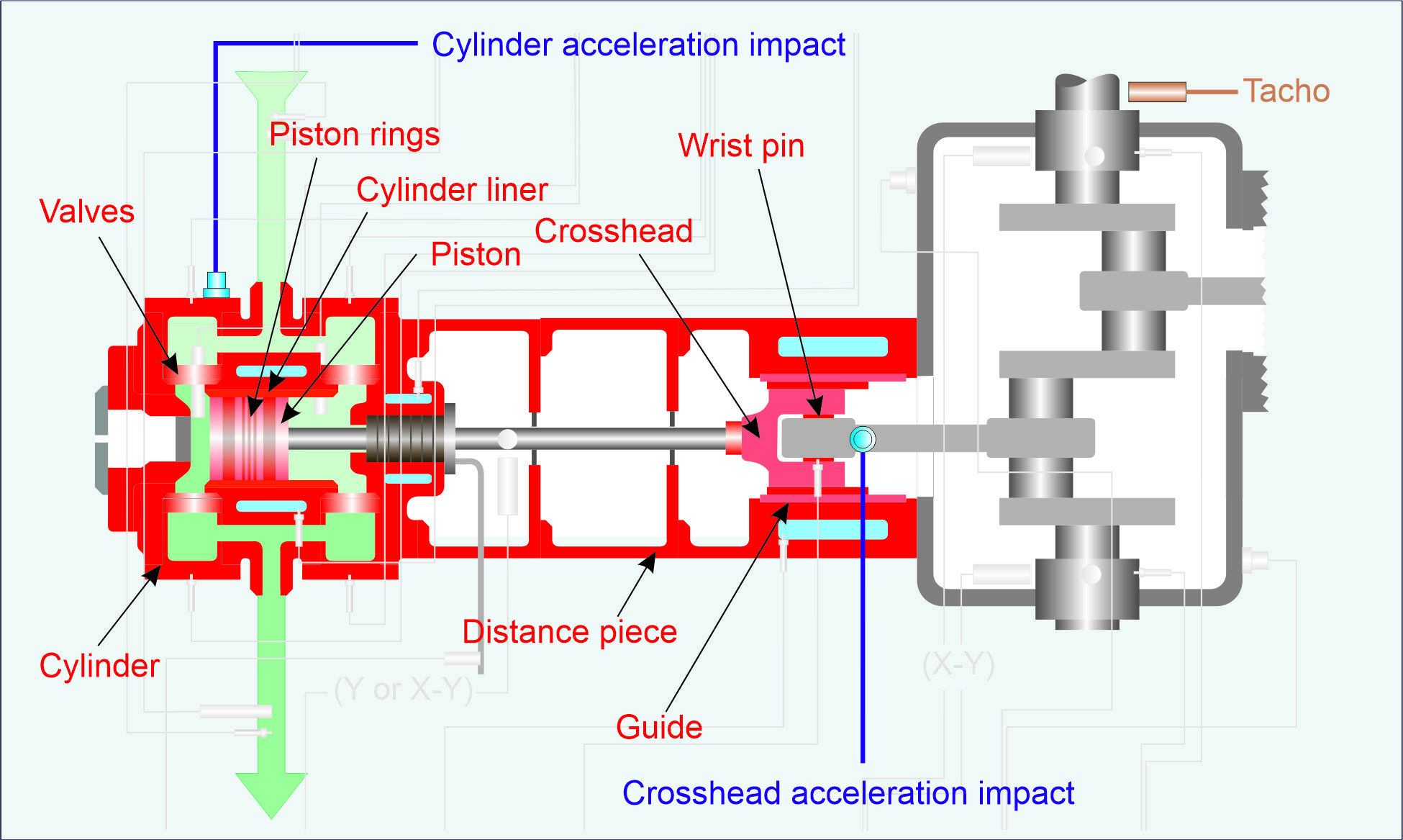
Figure 5. Accelerometer (blue) and tachometer (brown) sensor locations shown for monitoring the components shown in red: Crosshead (right), distance piece (centre) and cylinder components (left).
Plots
These are the primary plots used for displaying raw signals and descriptors from the crosshead and cylinder accelerometers for diagnostic purposes:
- Time waveform vs crank angle: vibration, rod load, and/or pressure often overlay each other (see Figures 1, 2, and 3). This plot also can include segments (see Figures 2 and 3).
- Non-synchronised time waveform plot vs time: raw signal, where several revolutions can be viewed simultaneously.
- Trend: individual segments, impact count, overall vibration, and more can be displayed individually, vs time or together with other scalar values, such as process and performance parameters.
Condition monitoring strategy and data management
All the monitoring techniques discussed in this article are essential tools for fault detection and diagnostics of reciprocating compressors, and for ultimately gaining insight into the machine health and maintenance planning. Unfortunately, these techniques are not enough on their own.
The acceleration signal impacts occurring in a crosshead, cylinder, and distance piece can vary in amplitude and phase with regards to the specific crank angle position. This is due to operating conditions, such as capacity control, speed, gas properties, suction and discharge pressure and temperature.
For early and reliable automatic fault detection, operators can monitor individual segment alarm limits and impact count scalar values in specific machine states.
For even greater reliability, the descriptors should not be monitored alone but correlated with other measurements, such as process and performance parameters. This includes valve temperatures, pressure-based performance parameters, and even other vibration measurements, such as the piston rod displacement or the frame vibration. This not only improves diagnostic reliability, but also provides better insight into the development of potential failures.
Finally, for optimal monitoring reliability and transparency, an enterprise-wide data management system can be employed. This can improve visualisation, event alarming, notification, and analysis. This can include automatic diagnostic support, artificial intelligence (AI), and machine learning (ML), all of which can reduce the IT infrastructure required for standalone monitoring systems.
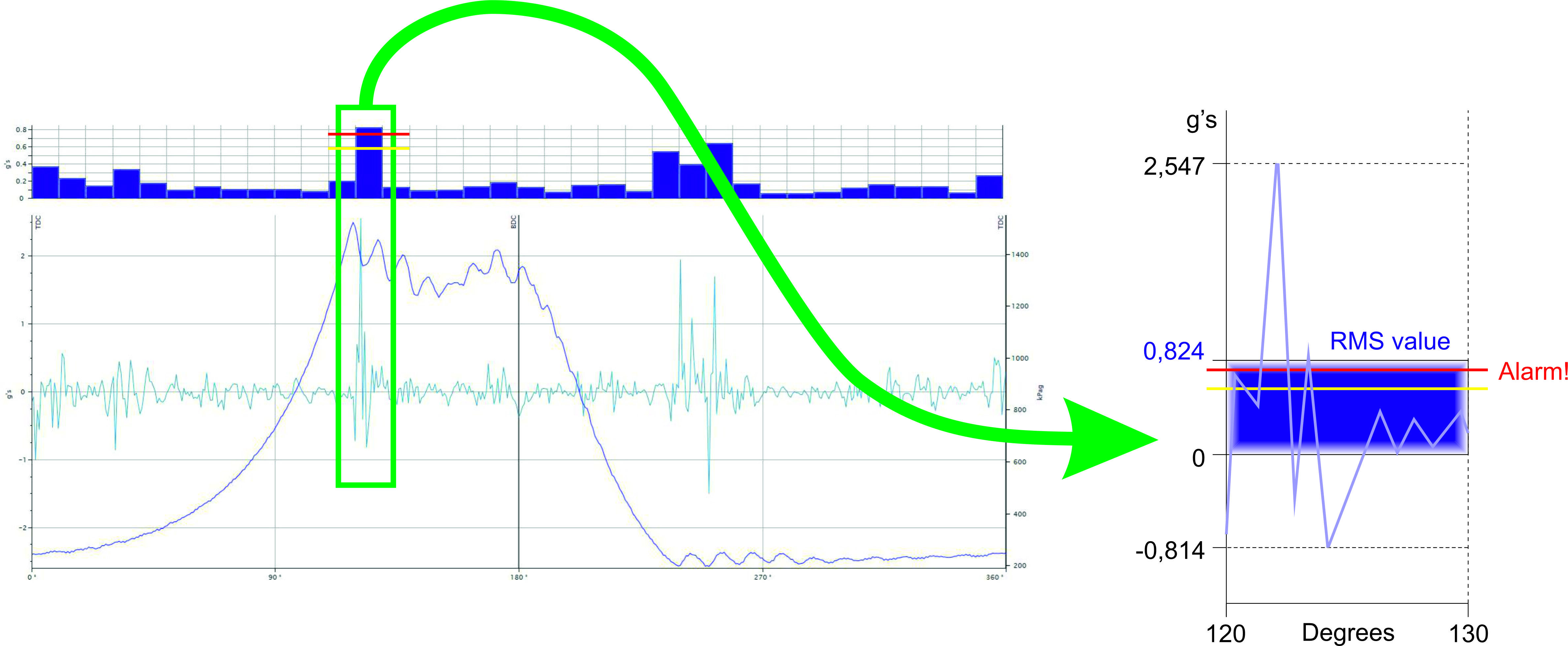
Figure 6. Vibration segment definition. For each vibration segment, the segment height is the root mean square value (RMS) of the corresponding time waveform section. In this example for the cylinder time signal waveform, the selected vibration segment is for 120 - 130° crank rotation.
Summary
There are many kinds of monitoring techniques available for reciprocating compressors, due to the reciprocating action of the running gear, but the actual requirements and priority of these depend on the specific application. However, vibration impact is the most important aspect for nearly every application, especially for crosshead and valves. Nevertheless, the vibration descriptors should be monitored to individual alarms with respect to the operating conditions.